Galloping Gertie
July 1, 1940 — the third-longest suspension span on Earth opens across the Tacoma Narrows. November 7, 1940 — she twists herself into Puget Sound. The federal plates still show the geometry. The failure was not a textbook “resonance match.” It was self-excited torsional flutter.

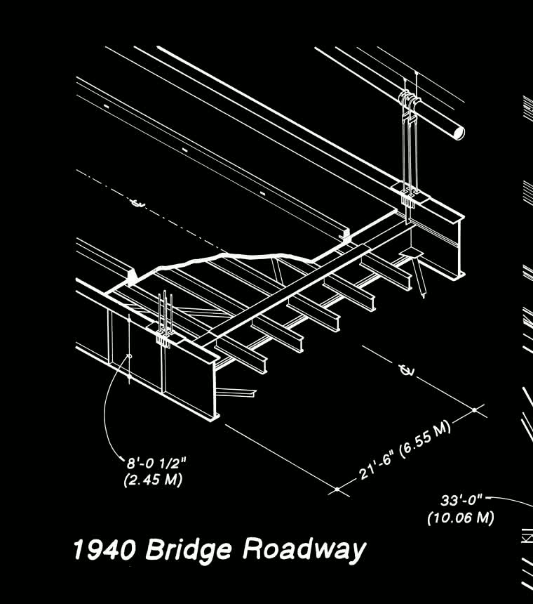
Leon Moisseiff’s 1940 Narrows Bridge was built to look like a blade — deflection-theory light, long, and narrow. Same 2,800-foot (853 m) main span the 1950 westbound span still uses. Between the cables: 39 feet. Roadway: 26 feet (two lanes). Stiffening: a pair of solid plate girders, 8′-0½″ deep, one along each edge, webs parallel to traffic. A southwest wind did not vent through them. It met a continuous steel wall.
// Load path — how the span carries gravity
Before wind ever mattered, the bridge had to hang. Dead load and live load on the deck travel up the suspenders (hangers) in tension, into the two main cables (also tension). Each cable rides a saddle atop a tower: the cable force pushes the tower into compression and throws horizontal thrust into the pier foundations. Cable ends do not “stop” at the towers — they run through the side spans and terminate in massive anchorage blocks (~52,500 tons of concrete each, WSDOT) that hold the pull with weight and earth.
Under uniform load the main-span cable is nearly a parabola. Horizontal tension H is essentially constant; tension is highest near the towers where the slope is steepest:
Tmax ≈ H √(1 + (4d/L)²)
L = 2,800 ft · sag ratio 1:12 ⇒ d ≈ 233 ft (WSDOT) · w ≈ half of 5,700 lb/ft center-span weight ≈ 2,850 lb/ft per cable (deck only; estimate)
H ≈ 1.20×10⁷ lb ≈ 6,000 short tons (≈ 175 MN)
Tmax ≈ 6,300 short tons (≈ 184 MN) at the tower — order-of-magnitude; omits cable self-weight and side-span share. WSDOT “weight sustained by cables” 11,250 tons (both cables) is the same ballpark.
Main cables: 17.5 in diameter, 6,308 No. 6 wires each. That is how a real suspension bridge works on a calm day. Flutter is what happens when the deck cannot refuse a dance the wind invites.
// Deck stiffness — why the ribbon was lethal
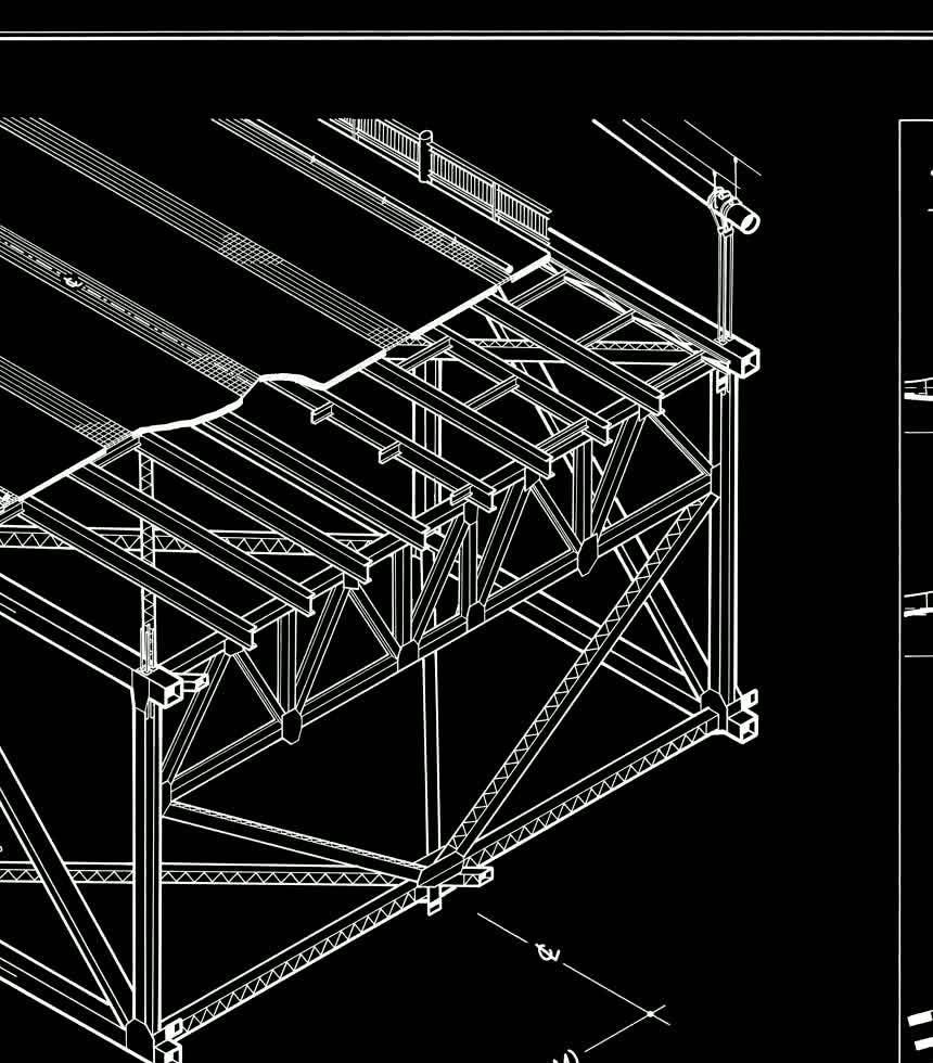
Span-to-girder-depth ratio ≈ 350:1. Width-to-span (cables) ≈ 1:72 — unprecedented among contemporaries (Golden Gate was about 1:47). Shallow solid girders give little vertical bending stiffness and, worse, a tiny torsional constant: a thin closed ribbon between two cables only 39 ft apart. The 1950 rebuild threw out the ribbon for a deeper open stiffening truss — more depth for bending, real torsional resistance, and wind paths through the deck instead of around a sail.
// Wind — vertical gallop ≠ the kill shot
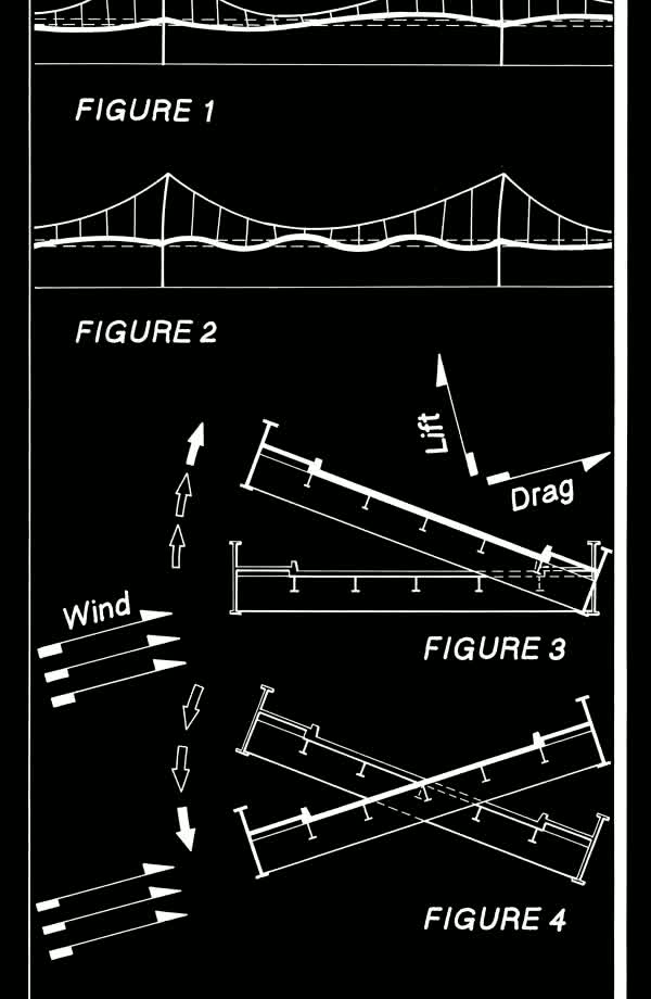
Air sliding past a blunt, solid face peels into alternating swirls — a Kármán vortex street. The HAER failure sheet draws lift-and-drag couples on the girder section (figs. 3–4). Early on, Gertie showed large vertical motion — enough that workers named her months before she fell. Vortex-related forcing and other aeroelastic effects belong in that early story.
Billah & Scanlan (1991): at the failure wind (~42 mph), a Strouhal estimate for an ~8 ft bluff depth sits near ~1 Hz. Farquharson’s destructive torsion ran about 0.2 Hz (roughly 12 cycles per minute). The clocks do not match. The fatal motion was self-excited torsional flutter — the deck’s own twist reshaped the flow and fed energy back in (effective negative damping), not a forced oscillator driven by an external vortex metronome.
// November 7 — sequence
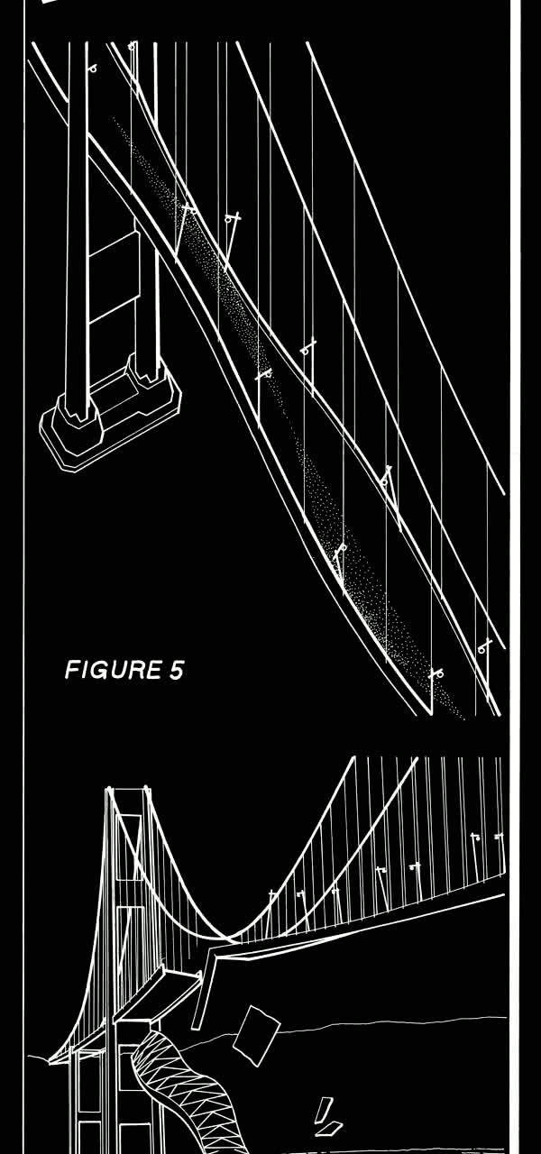
Morning of November 7, 1940: southwest wind building toward ~42 mph. Large vertical waves — familiar Gertie behavior. Shortly after 10:00, a cable band at mid-span on the north cable slipped (Carmody Board / WSDOT narrative), unbalancing the cable geometry and helping the shift into torsion. The deck’s twist then ran away under self-excitation. Suspenders ruptured. The main span tore and fell. Side spans and towers were wrecked; piers and anchorages largely held. Hundreds of wires in the north cable tore at the slipped band (period accounts cite roughly 350–500 of 6,308).
Carmody Board (1941), period language: excessive flexibility, shallow girders, and aerodynamic forces “like vortex shedding and self-excited torsional flutter.” Modern consensus backs the flutter / negative-damping reading (Billah & Scanlan), not classical forced resonance.
The 1950 rebuild kept the 2,800 ft main span and threw out the sail: deeper open stiffening truss, wider deck, hold-downs, later dampers. Wind-tunnel models became standard practice. Gertie’s wreck is still on the bottom — an artificial reef, and the opening page of every honest aeroelastic textbook. (Grokipedia: Tacoma Narrows Bridge (1940))
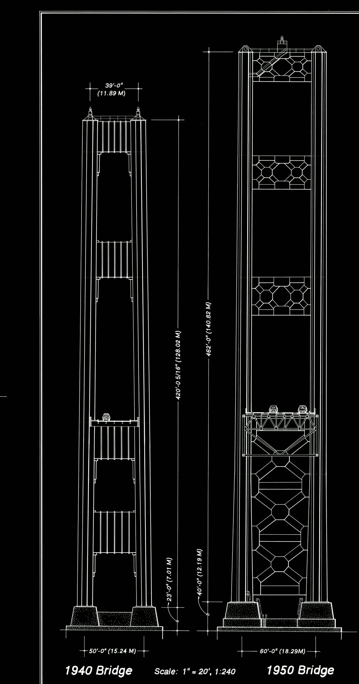

Plates: Historic American Engineering Record WA-99, Library of Congress / National Park Service, 1993. Public domain. Stats cross-checked to WSDOT Tacoma Narrows Bridge history. Mechanism line: Billah & Scanlan, Am. J. Phys. 59, 118 (1991). Click any sheet — full sheet 1 · full sheet 2.
Phases: CALM → VERTICAL (HEAVE) → TORSION ONSET → SELF-EXCITED FLUTTER. Collapse replay is torsional self-excitation (Billah & Scanlan) — not vortex “lock-in” to a natural bounce. Amplitudes are theatrical.